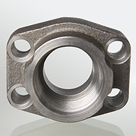
AFS T (3000 / 6000 PSI)
SAE screw-in flange, UN/UNF Product image


 Properties
| Standard |
SAE J 518 C ISO 6162 |
| Construction |
straight |
| Design |
SAE screw-in flange |
| Mounting |
Screw bore hole |
| Scope of supply |
flange only |
| Material |
S355J2G3 (ST52.3) |
| Surface |
black oiled |
 Note
Note
The stated maximum working pressure relates to the flange. The actual working pressure is determined by the pipe (wall thickness) and the quality of the pipe.
 Item
Item

Sort upwards
Sort downwards
 Identification Identification |
Pressure series | PB 10.9 (bar) |
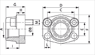
Size | A | Ø B (mm) |
C (mm) |
D (mm) |
E (mm) |
F (mm) |
G (mm) |
H (mm) |
I (mm) |
L (mm) |
|---|---|---|---|---|---|---|---|---|---|---|---|---|---|
| AFS 80 T | 3000 PSI | 350 | 1/2" | UNF 3/4" -16 | 13 | 38,1 | 54 | 17,5 | 46 | 36 | 16 | 17 | 9,0 |
| AFS 100 T | 3000 PSI | 350 | 3/4" | UNF 1 1/16" -12 | 19 | 47,6 | 65 | 22,3 | 50 | 36 | 18 | 23 | 11,0 |
| AFS 102 T | 3000 PSI | 315 | 1" | UN 1.5/16" -12 | 25 | 52,4 | 70 | 26,2 | 55 | 38 | 18 | 23 | 11,0 |
| AFS 104 T | 3000 PSI | 250 | 1.1/4" | UN 1.5/8" -12 | 32 | 58,7 | 79 | 30,2 | 68 | 41 | 21 | 23 | 11,5 |
| AFS 106 T | 3000 PSI | 200 | 1.1/2" | UN 1.7/8" -12 | 38 | 69,9 | 93 | 35,7 | 78 | 45 | 25 | 23 | 13,5 |
| AFS 401 T | 6000 PSI | 400 | 1/2" | UNF 3/4" -16 | 13 | 40,5 | 54 | 18,2 | 46 | 36 | 16 | 17 | 9,0 |
| AFS 402 T | 6000 PSI | 400 | 3/4" | UNF 1 1/16" -12 | 19 | 50,8 | 71 | 23,8 | 55 | 35 | 21 | 23 | 11,0 |
| AFS 403 T | 6000 PSI | 400 | 1" | UN 1.5/16" -12 | 25 | 57,2 | 81 | 27,8 | 65 | 42 | 25 | 23 | 13,0 |
| AFS 404 T | 6000 PSI | 400 | 1.1/4" | UN 1.5/8" -12 | 32 | 66,7 | 95 | 31,8 | 78 | 45 | 27 | 23 | *1 |
| AFS 405 T | 6000 PSI | 400 | 1.1/2" | UN 1.7/8" -12 | 38 | 79,4 | 112 | 36,5 | 94 | 50 | 30 | 23 | 17,0 |
PN = Nominal pressure PB = Max. operating pressure
*1) = 15.0 for metric screws; 13.5 for UNC screws
 Product versions

This product is also available in the following designs:
- AFS T M (3000 / 6000 PSI)
- SAE screw-in flange, UN/UNF, with metric screw set and O-ring
- AFS T U (3000 / 6000 PSI)
- SAE screw-in flange, UN/UNF, with UNC screw set and O-ring
Disclaimer
Despite careful checking, we cannot guarantee the accuracy of all information included on this site, and we accept no liability.
All data and information in our online catalogue are based on currently valid standards and the regulations from the employer's liability insurance association. Product safety can only be guaranteed when our assembly instructions are carefully observed. Non-adherence to these regulations can affect product operation and functioning and result in a loss of warranty. Our warranty is only valid for HANSA-FLEX products. Our products are constantly subject to further development and technical changes are therefore possible.


 Select language
 Bulgarian (Български)
 Chinese (汉语)
 Croatian (Hrvatski)
 Czech (Čeština)
 Dutch (Nederlands)
 Estonian (Eesti)
 French (Français)
 German (Deutsch)
 Hungarian (Magyar)
 Italian (Italiano)
 Latvian (Latviešu)
 Lithuanian (Lietuvių k.)
 Polish (Polski)
 Portuguese (Português)
 Romanian (Română)
 Russian (Русский)
 Serbian (Српска)
 Slovakian (Slovenčina)
 Slovenian (Slovenščina)
 Spanish (Español)
 Turkish (Türkçe)

