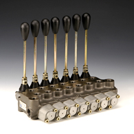
HK BM40
Hand-operated directional control valve BM 40 Product image

 Properties
| Design |
Monobloc valve for pipeline installation |
| Scope of supply |
without hand lever (please order separately) |
| Operating pressure |
P, A, B: max. 220bar / T: max. 80bar |
| Volumetric flow |
max. 40 l/min (note characteristic curves) |
| Connection |
P + T = G 3/8"; P2 + T2 = G 1/2"; A + B = G 3/8" |
 Description
compact design
Integrated non-return valve and pressure relief valve 90-220bar (valve must be set)
spool with control notches for sensitive operation
Up to 7 sections possible.
 Item
Item

Sort upwards
Sort downwards
 Identification Identification |
Circuit diagram | I (mm) |
L (mm) |
Design | Weight (kg) |
|---|---|---|---|---|---|
| HK BM40 A1 |   |
55 | 90 | 1 Section (A1) | 2,5 |
| HK BM40 K16 |   |
55 | 90 | 1 Section (K16) | 2,5 |
| HK BM40 L12 |   |
55 | 90 | 1 Section (L12) | 2,5 |
| HK BM40 A1X2 |   |
90 | 125 | 2 Section (2xA1) | 3,7 |
| HK BM40 A1 K16 |   |
90 | 125 | 2 Section (1xA1; 1xK16) | 3,7 |
| HK BM40 A1 L12 |   |
90 | 125 | 2 Section (1xA1; 1xL12) | 3,7 |
| HK BM40 A1X3 |   |
125 | 160 | 3 Section (3xA1) | 5,0 |
| HK BM40 A1X2 K16 |   |
125 | 160 | 3 Section (2xA1; 1xK16) | 5,0 |
| HK BM40 A1X2 L12 |   |
125 | 160 | 3 Section (2xA1; 1xL12) | 5,0 |
| HK BM40 A1X4 |   |
160 | 195 | 4 Section (4xA1) | 6,2 |
| HK BM40 A1X3 K16 |   |
160 | 195 | 4 Section (3xA1; 1xK16) | 6,2 |
| HK BM40 A1X3 L12 |   |
160 | 195 | 4 Section (3xA1; 1xL12) | 5,0 |
| HK BM40 A1X5 |   |
195 | 230 | 5 Section (5xA1) | 7,4 |
| HK BM40 A1X4 K16 |   |
195 | 230 | 5 Section (4xA1; 1xK16) | 7,4 |
| HK BM40 A1X4 L12 |   |
195 | 230 | 5 Section (4xA1; 1xL12) | 7,4 |
| HK BM40 A1X6 |   |
230 | 265 | 6 Section (6xA1) | 8,6 |
| HK BM40 A1X5 K16 |   |
230 | 265 | 6 Section (5xA1; 1xK16) | 8,6 |
| HK BM40 A1X5 L12 |   |
230 | 265 | 6 Section (5xA1; 1xL12) | 8,6 |
| HK BM40 A1X7 |   |
265 | 300 | 7 Section (7xA1) | 9,8 |
| HK BM40 A1X6 K16 |   |
265 | 300 | 7 Section (6xA1; 1xK16) | 9,8 |
| HK BM40 A1X6 L12 |   |
265 | 300 | 7 Section (6xA1; 1xL12) | 9,8 |
 Ordering information
Please order hand lever separately - 1 lever per section!
The valves are available in the stated basic version. For other possible configurations for actuators and piston types see graphic.
Example configuration HKBM40A1L12:
- Valve type HKBM40
- Section 1 with piston type A and actuator 1
- Section 2 with piston type L and actuator 12
 Accessories
 Spare parts
Disclaimer
Despite careful checking, we cannot guarantee the accuracy of all information included on this site, and we accept no liability.
All data and information in our online catalogue are based on currently valid standards and the regulations from the employer's liability insurance association. Product safety can only be guaranteed when our assembly instructions are carefully observed. Non-adherence to these regulations can affect product operation and functioning and result in a loss of warranty. Our warranty is only valid for HANSA-FLEX products. Our products are constantly subject to further development and technical changes are therefore possible.


 Select language
 Bulgarian (Български)
 Chinese (汉语)
 Croatian (Hrvatski)
 Czech (Čeština)
 Dutch (Nederlands)
 Estonian (Eesti)
 French (Français)
 German (Deutsch)
 Hungarian (Magyar)
 Italian (Italiano)
 Latvian (Latviešu)
 Lithuanian (Lietuvių k.)
 Polish (Polski)
 Portuguese (Português)
 Romanian (Română)
 Russian (Русский)
 Serbian (Српска)
 Slovakian (Slovenčina)
 Slovenian (Slovenščina)
 Spanish (Español)
 Turkish (Türkçe)

